我拿到的開發(fā)板實(shí)際板載的 MCU 是 GD32F310G8,QFN28pin 封裝,基于 ARM CORTEX M4 內(nèi)核,主頻 72MHz, 芯片內(nèi)置 64KB flash,8KB SRAM, 兩路 I2C 外設(shè)。
整體概述
首先感謝極術(shù)社區(qū)給我試用GD32開發(fā)板的機(jī)會,讓我體驗(yàn)一下近幾年國產(chǎn)MCU開發(fā)體驗(yàn)。該芯片是基于arm cortex-M4內(nèi)核,主頻72Mhz,flash 64k,ram 8k,以及豐富的外設(shè)。
本次試用是一個讀取三軸加速度計(jì)的實(shí)驗(yàn),主要使用的是硬件iic。
硬件連接
傳感器介紹
SC7A20 是一款高精度 12bit 數(shù)字三軸加速度傳感器芯片,內(nèi)置功能 更豐富,功耗更低,體積更小,測量更精確。
芯片通過 IC2/SPI 接口與 MCU 通信,加速度測量數(shù)據(jù)以中斷方式或 查詢方式獲取。INT1和INT2中斷管腳提供多種內(nèi)部自動檢測的中斷信號, 適應(yīng)多種運(yùn)動檢測場合,中斷源包括 6D/4D 方向檢測中斷信號、自由落體 檢測中斷信號、睡眠和喚醒檢測中斷信號、單擊和雙擊檢測中斷信號。
芯片內(nèi)置高精度校準(zhǔn)模塊,對傳感器的失調(diào)誤差和增益誤差進(jìn)行精確補(bǔ)償。 ±2G、±4G、±8G 和±16G 四種可調(diào)整的全量程測量范圍,靈活測量外 部加速度,輸出數(shù)據(jù)率 1HZ 和 400HZ 間可選。
軟件功能
該軟件主要使用了GD32開發(fā)板的硬件iic,外部中斷以及串口,這三部分功能,串口的配置在其他文章的當(dāng)中已經(jīng)有敘述,本文只主要介紹iic和外部中斷的使用.
硬件iic
初始化gpio

配置硬件iic
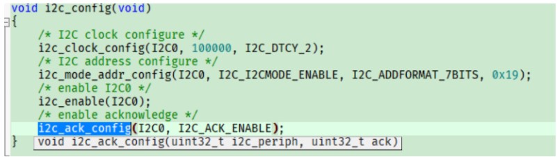
根據(jù)廠商提供的庫函數(shù)(具體參考gd32f3x0_i2c.c文件),我們可以很容易的初始化iic。剩下的就是對傳感器進(jìn)行配置了,該傳感器需要配置寄存器較多,廠商直接提供了一份demo程序,只需要適配讀取寫入的接口就可以很快的使用了。
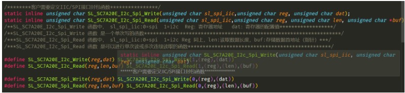
我需要做的就是把iic的讀取和寫入進(jìn)行適配適配函數(shù)如下:
void I2C_LeaderWrite(uint16_t followerAddress, , uint8_t targetAddress, uint8_t *txBuff,
uint8_t numBytes) {
/* wait until I2C bus is idle */
while (i2c_flag_get(I2C0, I2C_FLAG_I2CBSY))
;
/* send a start condition to I2C bus */
i2c_start_on_bus(I2C0);
/* wait until SBSEND bit is set */
while (!i2c_flag_get(I2C0, I2C_FLAG_SBSEND))
;
/* send slave address to I2C bus */
i2c_master_addressing(I2C0, followerAddress, I2C_TRANSMITTER);
/* wait until ADDSEND bit is set */
while (!i2c_flag_get(I2C0, I2C_FLAG_ADDSEND))
;
/* clear ADDSEND bit */
i2c_flag_clear(I2C0, I2C_FLAG_ADDSEND);
/* wait until the transmit data buffer is empty */
while (!i2c_flag_get(I2C0, I2C_FLAG_TBE))
;
for (i = 0; i < numBytes; i++) {
/* data transmission */
i2c_data_transmit(I2C0, txBuff[i]);
/* wait until the TBE bit is set */
while (!i2c_flag_get(I2C0, I2C_FLAG_TBE))
;
}
/* send a stop condition to I2C bus */
i2c_stop_on_bus(I2C0);
/* wait until stop condition generate */
while (I2C_CTL0(I2C0) & 0x0200)
;
}
void I2C_LeaderRead(uint16_t followerAddress, uint8_t targetAddress, uint8_t *rxBuff,
uint8_t numBytes) {
/* wait until I2C bus is idle */
while (i2c_flag_get(I2C0, I2C_FLAG_I2CBSY))
;
/* send a start condition to I2C bus */
i2c_start_on_bus(I2C0);
/* wait until SBSEND bit is set */
while (!i2c_flag_get(I2C0, I2C_FLAG_SBSEND))
;
/* send slave address to I2C bus */
i2c_master_addressing(I2C0, followerAddress, I2C_TRANSMITTER);
/* wait until ADDSEND bit is set */
while (!i2c_flag_get(I2C0, I2C_FLAG_ADDSEND))
;
/* clear the ADDSEND bit */
i2c_flag_clear(I2C0, I2C_FLAG_ADDSEND);
/* wait until the transmit data buffer is empty */
while (SET != i2c_flag_get(I2C0, I2C_FLAG_TBE))
;
/* enable I2C0*/
i2c_enable(I2C0);
/* send the EEPROM's internal address to write to */
i2c_data_transmit(I2C0, targetAddress);
/* wait until BTC bit is set */
while (!i2c_flag_get(I2C0, I2C_FLAG_BTC))
;
/* send a start condition to I2C bus */
i2c_start_on_bus(I2C0);
/* wait until SBSEND bit is set */
while (!i2c_flag_get(I2C0, I2C_FLAG_SBSEND))
;
/* send slave address to I2C bus */
i2c_master_addressing(I2C0, followerAddress, I2C_RECEIVER);
/* wait until ADDSEND bit is set */
while (!i2c_flag_get(I2C0, I2C_FLAG_ADDSEND))
;
/* clear the ADDSEND bit */
i2c_flag_clear(I2C0, I2C_FLAG_ADDSEND);
/* while there is data to be read */
for (int i = 0; i < numBytes; i++) {
/* code */
/* read a data from I2C_DATA */
rxBuff[i++] = i2c_data_receive(I2C0);
/* send a stop condition */
i2c_stop_on_bus(I2C0);
}
/* wait until the stop condition is finished */
while (I2C_CTL0(I2C0) & 0x0200)
;
/* enable acknowledge */
i2c_ack_config(I2C0, I2C_ACK_ENABLE);
i2c_ackpos_config(I2C0, I2C_ACKPOS_CURRENT);
}
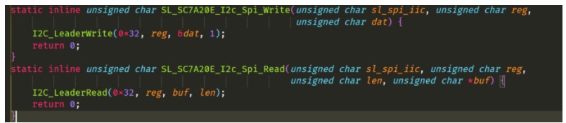
然后把這兩個函數(shù)適配:
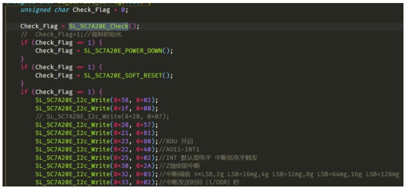
然后對傳感器進(jìn)行設(shè)置
外部中斷
使用外部中斷可以使用用于喚醒mcu,這對設(shè)計(jì)低功耗的產(chǎn)品很有意義,當(dāng)傳感器超過設(shè)定的閾值的時(shí)候,那么就會產(chǎn)生一個中斷來通知mcu,需要進(jìn)一步的處理數(shù)據(jù),外部中斷的配置如下所示:
void exit_wakeup_interrupt_config(void)
{
/* configure the priority group */
nvic_priority_group_set(NVIC_PRIGROUP_PRE2_SUB2);
/* enable the key wakeup clock */
rcu_periph_clock_enable(RCU_GPIOA);
rcu_periph_clock_enable(RCU_CFGCMP);
/* configure button pin as input */
gpio_mode_set(GPIOA, GPIO_MODE_INPUT, GPIO_PUPD_NONE, GPIO_PIN_0);
/* enable and set key wakeup EXTI interrupt to the higher priority */
nvic_irq_enable(EXTI0_1_IRQn, 2U, 0U);
/* connect key wakeup EXTI line to key GPIO pin */
syscfg_exti_line_config(EXTI_SOURCE_GPIOA, EXTI_SOURCE_PIN0);
/* configure key wakeup EXTI line */
exti_init(EXTI_0, EXTI_INTERRUPT, EXTI_TRIG_FALLING);
exti_interrupt_flag_clear(EXTI_0);
}
數(shù)據(jù)處理
由于我們使用的是三軸傳感器,對于姿態(tài)位置的計(jì)算并不是很精確,因此,此處只用簡單角度計(jì)算,傾角的計(jì)算原理如下
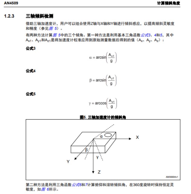
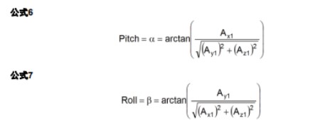
計(jì)算代碼如下:
#define DEG_TO_RAD(x) ((x) * 0.01745329252)
#define RAD_TO_DEG(x) ((x) * 57.2957795131)
void angle_calculation() {
double pitch, roll, paw;
pitch = atan(xyz_mg[X] / sqrt(pow(xyz_mg[Y], 2) + pow(xyz_mg[Z], 2)));
roll = atan(xyz_mg[Y] / sqrt(pow(xyz_mg[X], 2) + pow(xyz_mg[Z], 2)));
paw = atan(sqrt(pow(xyz_mg[X], 2) + pow(xyz_mg[Y], 2)) / xyz_mg[Z]);
printf('[RAD]pitch:%.2f | roll:%.2f | paw:%.2f rn', pitch, roll, paw);
printf('[DEG]pitch:%.2f° | roll:%.2f° | paw:%.2f° rn', RAD_TO_DEG(pitch), RAD_TO_DEG(roll),
RAD_TO_DEG(paw));
}
上一篇:GD32MCU最小系統(tǒng)構(gòu)成條件
下一篇:STM32 MPU是什么產(chǎn)品?了解嵌入式系統(tǒng)中微處理器的新變化
推薦閱讀最新更新時(shí)間:2025-07-04 10:18

 基于51單片機(jī)的壓力檢測報(bào)警
 時(shí)間觸發(fā)嵌入式系統(tǒng)設(shè)計(jì)模式(使用8051系列微控制器開發(fā)可靠應(yīng)用)
 電子工程師必備-元器件應(yīng)用寶典
設(shè)計(jì)資源 培訓(xùn) 開發(fā)板 精華推薦
- 【下載】LAT1526 利用SPI的下溢實(shí)現(xiàn)回顯功能
- 【下載】LAT1509 STM32G0B1的FDCAN進(jìn)行通信丟包和多包案例分享
- 【下載】LAT1511 運(yùn)行Ux_Host_HUB_HID_MSC通過Hub連接U盤讀寫不穩(wěn)定問題分析
- 【下載】LAT1466 USB x Device HID Standalone的移植
- 【下載】LAT1488 STM32 USBxDevice MSC standalone移植示例
- 【下載】LAT1482 STM32G0單線串口通信幀錯誤問題解析

- 基于單片機(jī)的LED自適應(yīng)調(diào)光系統(tǒng)
- 智能小車主控系統(tǒng)電路設(shè)計(jì)
- Microchip 升級數(shù)字信號控制器(DSC)產(chǎn)品線 推出PWM 分辨率和 ADC 速度業(yè)界領(lǐng)先的新器件
- 意法半導(dǎo)體STM32MP23x:突破成本限制的工業(yè)AI應(yīng)用核心
- 意法半導(dǎo)體推出用于匹配遠(yuǎn)距離無線微控制器STM32WL33的集成的匹配濾波芯片
- ESP32開發(fā)板連接TFT顯示屏ST7789跳坑記
- 如何讓ESP32支持analogWrite函數(shù)
- LGVL配合FreeType為可變字體設(shè)置字重-ESP32篇
- 使用樹莓派進(jìn)行 ESP32 Jtag 調(diào)試

- 適用于汽車應(yīng)用的 LT3973HMSE-3.3 3.3V 降壓轉(zhuǎn)換器的典型應(yīng)用
- R_08_V30基于IPS2電機(jī)換向傳感器的設(shè)計(jì)
- 使用 Microchip Technology 的 PIC16C782 的參考設(shè)計(jì)
- 使用 LT1054CSW 基本型電壓逆變器 / 穩(wěn)壓器的典型應(yīng)用
- 使用 LTC3637EDHC 4V 至 76V 輸入至 1.8V 超級電容器充電器的典型應(yīng)用
- 儀表用 ADC 驅(qū)動器
- EN6310QA 1A PowerSoC 電壓模式同步 PWM 降壓與集成電感器的典型應(yīng)用
- STEVAL-ISV012V1,使用 L6924D 高達(dá) 5 W 太陽能電池充電器的演示板,用于單節(jié)鋰離子和鋰聚合物電池
- 適用于汽車應(yīng)用的 A5974D 正降壓-升壓穩(wěn)壓器的典型應(yīng)用電路
- 使用 NXP Semiconductors 的 TDA2582Q 的參考設(shè)計(jì)


- 消費(fèi)科技品牌Nothing采用Ceva的RealSpace軟件 為耳機(jī)和耳塞用戶帶來身臨其境的空間音頻體驗(yàn)
- Nordic Semiconductor推出高度集成 nPM1304 電源管理 IC支持小尺寸電池產(chǎn)品
- 村田發(fā)布首款搭載XBAR技術(shù)的高頻濾波器
- 普源精電(RIGOL)發(fā)布多通道波形發(fā)生及先進(jìn)計(jì)算解決方案
- 艾邁斯歐司朗SYNIOS產(chǎn)品以更多創(chuàng)新和更多功能賦能汽車設(shè)計(jì)更多驚喜
- 推動我國自動駕駛道路測試工作的幾點(diǎn)建議
- 深度學(xué)習(xí)預(yù)測可解決自動駕駛等問題
- 全球及我國汽車操作系統(tǒng)發(fā)展現(xiàn)狀分析
- 針對我國汽車操作系統(tǒng)發(fā)展情況提出三點(diǎn)建議
- 動力電池為什么會有安全問題?
- STM32使用FSMC總線方式控制LCD的方法
- STM32中如何使用printf()函數(shù)?
- 煤礦數(shù)字通信系統(tǒng)設(shè)計(jì)
- STM32-串口超時(shí)判斷方式接收未知長度數(shù)據(jù)
- STM32單片機(jī)ISP燒寫
- 上汽集團(tuán)將加快研發(fā)G20FC燃料電池轎車
- 北京斯凱瑞利推出中國國內(nèi)首款用于前裝車載ETC的SKY6650芯片
- LoRa 和LoRaWAN升級,你需要知道的有哪些
- 你的智能汽車能否聰明的繞開物體
- 2.5D視覺系統(tǒng)“Eyes”實(shí)現(xiàn)機(jī)器人應(yīng)用的極致簡易操作


 京公網(wǎng)安備 11010802033920號